🚗 W806#
W806 What is it??#
W806 It is a QFN56 package, 6mm x 6mm mcu. This chip is interchangeable with the combined Air103..
LuatOS What functions are provided for it#
Based on Lua 5.3.6 with 95% native library support
Adapts to the LuaTask and provides extremely friendly
sys.luaFile system size 112KB, format littlefs 2.1.
Support plug-in PSRAM, maximum 8MB
gpioGPIO Pin control function (provided after the mapping table)uartSerial port input and output function, support uart0 (chip log/debug/brush machine)/uart1 ~ 4 (user available)i2ciic Bus master function, and comes with a variety of temperature and humidity sensor driverdispi2c based display support, such SSD1306einkSupport a variety of ink screenlcdSupport multiple color SPI screenlvglSupports all LVGL native components and animation effects, and embedded Chinese fontszbuffOperate memory byte arrays like C language, efficient and reliablejsonlua bi-directional conversion between object and json stringlogSimple log functionwdtHardware watchdog, security protectionpwmMultiple PWM output pins, there is a multiplexing relationshipadc2 adc channel external level detection, an internal temperature detectionsensorSingle bus driver, default support DS18B20pmPower management for low-power mode entry and timed wake-uphwtimerhardware timer (in development)rtcReal-time clock (under development)sdioRead and write TF card through SDIO hardware interfacemcuMain frequency adjustment, minimum to 2M (need to reduce uart baud rate)
LuatOS Large QQ group: 1061642968
Special Notes#
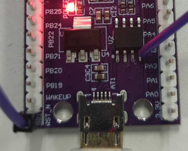
Since the reset pin of W806 development board is not connected to rts of serial port chip, manual reset and download are required, which is troublesome during development. As shown in the figure below, connect the rts pin flying wire of the serial port chip to the reset pin of the chip, and download the software to automatically reset the chip.
Compile Firmware#
If you only want to compile custom function firmware you can directly use Online Cloud Compilation to generate custom firmware. Without any environment installation, you can customize the selection of various functions.
I want to compile my own tutorial reference source code compilation tutorial to compile according to Air103
Burn Firmware#
After compiling the firmware, I believe you have obtained the firmware file with the. soc suffix. Here is how to burn the firmware into the device.
Tool Configuration#
First download the latest version of the Luatools:click me to download
It is recommended to create a new Luatools folder, put the exe file into it, and then open the exe file.
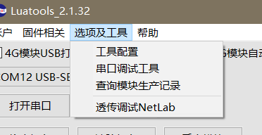
Select Options and Tools-Tool Configurations
On the uart tab, set the baud rate to 921600 and restart the software.
Burn#
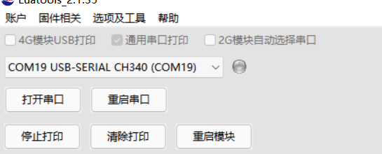
Connect the device to the computer through usb cable, you can see a new COM port, check universal serial port print, and select this COM port in the tool
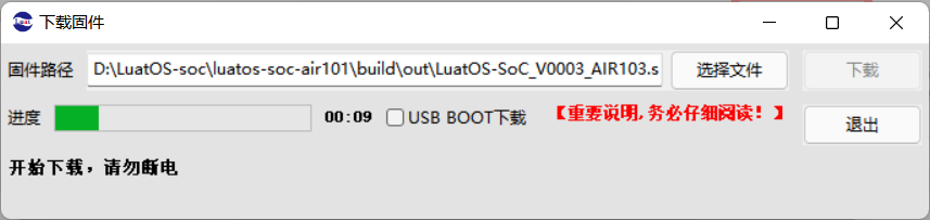
Click the “Download Firmware” button, select the soc file just downloaded, and download it directly. Because the rts pin of the serial chip of the w806 development board is not connected to the chip reset pin, you need to manually press the rst key on the board to restart after clicking the download. If the price increase is changed according to the special instructions, there is no need to reset it manually.
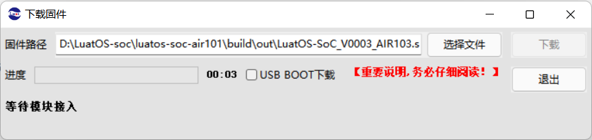
Wait for the progress bar to finish and the firmware will be downloaded successfully.
Burn Script#
Click the Project Management Test button and click Create Project in the bottom left corner to create a new project
Select the firmware used by the chip and select the script to download it.
demo The script of the class can be found in the /demo folder by going to LuatOS Official Warehouse.
Luatools The tool also automatically downloaded some example scripts of the official version, which can be seen in the resource \certain model \certain version \demo folder, and can be directly selected for burning test
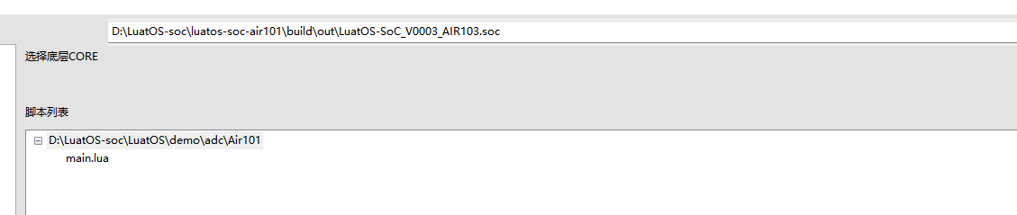
If the firmware version currently burned by the chip is the same as the firmware selected here, you can click “Download Script” to download only the script. On the contrary, it is recommended to click “Download Bottom Layer and Script” to perform a full brush.
View Log#
If the serial port is not opened, click “Open Serial Port” to view the log
If there is no response, you can try clicking restart serial port
GPIO Output-lighting#
This chapter will use the GPIO interface to control the LED lights of the development board to flash and be a lamp god.
Hardware preparation#
One development board and one usb cable
Software usage#
According to the schematic diagram, it can be found that the three lamps brought by the development board are PB0,1 and 2 control respectively, and the low level lights up.
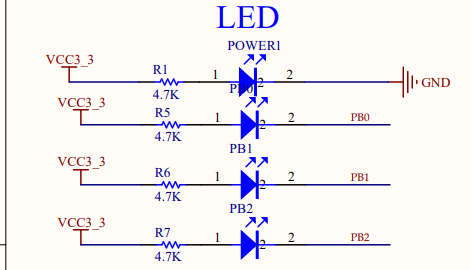
We look up the document of Air103/W806 LuatOS document and know that the pin number of PB0 is 16
According to the interface of GPIO operation, write a few lines of code simply. see the gpio folder of demo directory for the complete code.
local LED1 = gpio.setup(16, 0) -- PB0 Output mode
sys.taskInit(function()
    while 1 do
        log.info("LED Open")
        LED1(0)
        sys.wait(1000)
        log.info("LED Close")
        LED1(1)
        sys.wait(1000)
    end
end)
Burn to see the effect
Twinkle, twinkle, gpio output done
GPIO Input-Key#
I learned output control in the previous section. I’ll learn input while the iron is hot.
Hardware preparation#
One development board and one usb cable
Software usage#
The same routine, first look at the schematic diagram, RESET button don’t want to reset once pressed, then choose BOOT, that is PA0
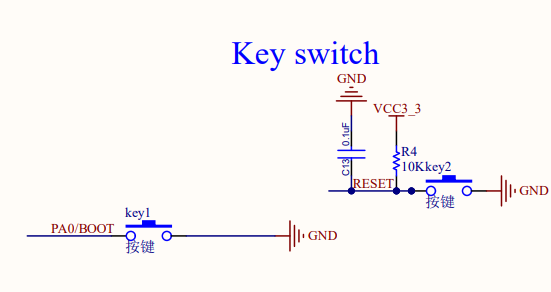
As usual, looking for Air103/W806 documents LuatOS documents shows that the pin number of PA0 is 0
According to the interface of gpio-GPIO Operation, simply write a few lines of code. For the complete code, see the gpio folder in the demo directory.
gpio.setup(0, function(val)
    log.info("PA0", val)
end, gpio.PULLUP)--The key is pressed to ground, so it needs to be pulled up
Burn, test it. Press the boot key and then release it, the log can see the normal trigger interrupt.
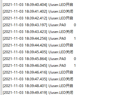
GPIO The input and output of we have completed our study.
PWM#
This chapter will use PWM to drive onboard LEDs to achieve a breathing light effect
Introduction#
PWM(Pulse Width Modulation , Pulse width modulation) is a method of digitally encoding the level of an analog signal. The duty cycle of a square wave is used to encode the level of a specific analog signal through pulses of different frequencies, so that a series of pulses of equal amplitude are obtained at the output, and these pulses are used to replace the required waveform.
Hardware preparation#
One development board and one usb cable
Software usage#
According to the previous GPIO study, we know that the onboard lamps are connected to PB0,1 and 2, and these pins all support PWM, so try to be a breathing lamp.
Check API and find that the use of PWM is very simple. Just open it directly, then adjust the duty cycle to adjust the brightness and code it. Complete code in demo’s pwm folder
sys.taskInit(function()
    while 1 do
        -- Imitation breathing light effect
        log.info("pwm", ">>>>>")
        for i = 100,1,-1 do
            pwm.open(0, 1000, i) -- Frequency 1000hz, duty cycle 0-100
            sys.wait(20)
        end
        sys.wait(1000)
        for i = 100,1,-1 do
            pwm.open(0, 1000, 100 - i)
            sys.wait(20)
        end
        gpio.setup(16,1)
        sys.wait(1000)
    end
end)
Burn to see the effect
The breathing light achieved
UART#
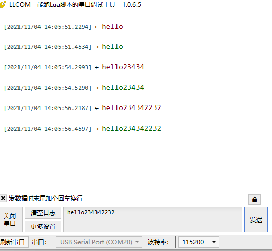
This chapter will learn how to configure the serial port and send the received data back through the serial port.
Introduction#
UART(Universal Asynchronous Receiver/Transmitter)Universal asynchronous transceiver, UART as a kind of asynchronous serial communication protocol, the working principle is to transmit each character of the data one by one. Is the most frequently used data bus in the application development process.
UART The characteristic of the serial port is to transmit data bit by bit in sequence. Two-way communication can be realized as long as two transmission lines. One line sends data while receiving data with another line. There are several important parameters for UART serial communication, namely baud rate, start bit, data bit, stop bit and parity bit. For two ports using UART serial communication, these parameters must match, otherwise the communication will not be completed normally.
Hardware preparation#
W806 One development board, one usb to serial port line
Software usage#
Looking at the document LuatOS Document, we can see that W806 has 5 uarts, of which uart0 is used for download and debugging, so let’s choose uart1. That is, PB6->TX then PB7->RX connect TX to serial line RX,RX to serial line TX, and then don’t forget to share the ground.
After connecting the line, we began to write the code. According to the API interface description of UART , we first initialized the serial port.
local result = uart.setup(
    UART_ID,--Serial port id
    115200,--Baud rate
    8,--data bit
    1--Stop bit
)
In order to do serial port data loopback, we must first learn how to receive serial port data. uart.on(id, event, func) in the interface registers serial port event callback, which is to interrupt callback reception. after receiving it, we will send it out through uart.write interface. theoretical analysis is completed and the code is uploaded.
-- Serial ID, Serial Read Buffer
local UART_ID, sendQueue = 1, {}
-- Serial port timeout, messages posted when the serial port is ready
--The example is 100ms, changed according to demand
local uartimeout, recvReady = 100, "UART_RECV_ID"
--Initialization
local result = uart.setup(
    UART_ID,--Serial port id
    115200,--Baud rate
    8,--data bit
    1--Stop bit
)
uart.on(UART_ID, "receive", function(uid, length)
    local s
    while true do--Ensure that you cannot lose packets after reading.
        s = uart.read(uid, length)
        if #s == 0 then break end
        table.insert(sendQueue, s)
    end
    sys.timerStart(sys.publish, uartimeout, recvReady)
end)
-- Send the received string to the serial port
sys.subscribe(recvReady, function()
    --Splice all received data
    local str = table.concat(sendQueue)
    -- Empty the buffer after reading the serial data
    sendQueue = {}
    --Note that printing will affect the running speed, and comment out after debugging.
    --log.info("uartTask.read length", #str, str:sub(1,100))
    uart.write(UART_ID,str) --Reply
    --Processing the received data here, this is the example
end)
For indefinite data reception, a timeout frame breaking mechanism is generally adopted, that is, a timer is started before a byte is received, and if the next byte is not received within a certain period of time, it is considered to be a packet of data.
Download the viewing effect and loop back the output after receiving the indefinite length data.
ADC#
This chapter will introduce you to the ADC features of LuatOS. The internal temperature will be read using the Air101 development board and printed in the log.
Introduction#
An analog-to-digital converter, or ADC for short, usually refers to an electronic component that converts an analog signal into a digital signal. A typical analog-to-digital converter converts an input voltage signal to an output digital signal. W806 chip has two 16-bit ADC, the highest sampling rate 1KHz。
Hardware preparation#
W806 One development board and one adjustable power supply
Software usage#
This time we first look for the document LuatOS document to see that in addition to reading the external IO voltage, we can also read the internal temperature and power supply voltage. This time we choose ADC0, which is the PA1 pin.
We connect the PA1 pin with an adjustable power supply (be sure to pay attention to the voltage not exceeding 2.4V)
According to the interface of ADC library library, write a few lines of code simply. See the adc folder of demo directory for the complete code.
sys.taskInit(function()
while 1 do
adc.open(0) -- ADC0 pin on the module-PA1, 0~2.4v, do not exceed the range of use!!!
adc.open(10) -- CPU Temperature
adc.open(11) -- VBAT Voltage, only the latest code is supported
sys.wait(500)
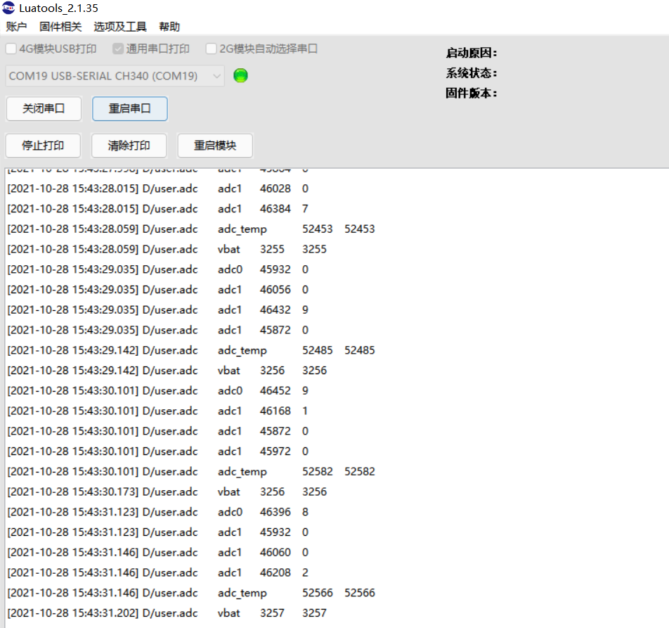
log.debug("adc", "adc0", adc.read(0))
log.debug("adc", "adc_temp", adc.read(10))
log.debug("adc", "vbat", adc.read(11))
sys.wait(500)
end
end)
Burn, observe the log
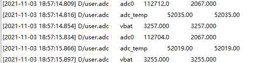
The external display PA1 voltage is 2.092V, and the measured ADC has certain errors. It is recommended to use it for threshold detection.
I2C#
This chapter will introduce you to the I2C features of LuatOS. W806 development board I2C will be used to read the temperature and humidity of the SHT30 sensor
Introduction#
I2C(Inter Integrated Circuit)The bus is a half-duplex, bidirectional two-wire synchronous serial bus developed by PHILIPS. The I2C bus only needs two signal lines to transmit data, one is a bidirectional data line SDA(serial data), and the other is a bidirectional clock line SCL(serial clock)
Hardware preparation#
W806 One development board and one SHT30 sensor
Software usage#
First of all, check the document LuatOS document and see the document that PA1 is SCL pin and PA4 is SDA pin. We attach the sensor to the board according to this definition.
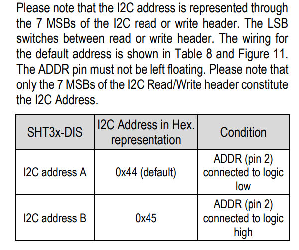
Start writing code, first find the interface description i2c-I2C Operation-LuatOS Document, initialize first, need the address, refer to SHT30 manual, the address is determined by the pin level of ADDR, my module is suspended, that is 0x44
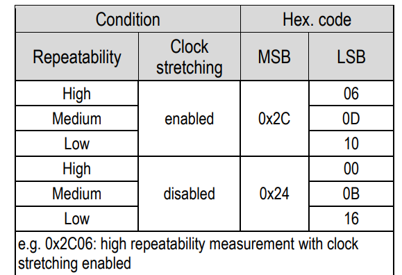
Knowing the address, let’s look at how to measure the temperature. The manual says that continuous measurement requires the command 0x2C06. Refer to the interface of LuatOS and direct i2c.send()
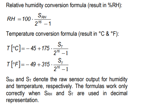
Then receive the data and calculate the actual temperature and humidity according to the formula in the manual.
The code is as follows. For the complete code, see the i2c folder in the demo directory.
sys.taskInit(function()
-- Initialize i2c with id 0
if i2c.setup(0, i2c.FAST, 0x44) == 1 then
log.info("Existence i2c0")
else
i2c.close(0) -- Turn off
end
while 1 do
local w = i2c.send(0, 0x44, string.char(0x2c, 0x06)) -- Send single acquisition command
sys.wait(10) -- Waiting for acquisition
local r = i2c.recv(0, 0x44, 6) -- Read data acquisition results
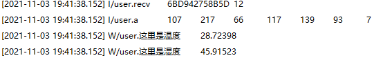
log.info("recv", r:toHex())
local a, b, c, d, e, f, g = string.unpack("BBBBBB", r)
log.info("a", a, b, c, d, e, f, g)
t = ((4375 * (a * 256 + b)) / 16384) - 4500 -- Calculate the temperature and humidity according to the formula given in the SHT30 sensor manual
h = ((2500 * (d * 256 + e)) / 16384)
log.warn("Here is the temperature ", t / 100) -print temperature
log.warn("Here is humidity ", h / 100) -print humidity
sys.wait(1000)
end
end)
Burn to check the results, it’s November, W806 makes my board no longer cold this winter.
SPI#
In this chapter, the hardware SPI of W806 will be used to read the ID of flah and print it.
Introduction#
SPI Serial Peripheral Interface (Serial Peripheral Interface) is an abbreviation, is a high-speed, full-duplex, synchronous communication bus, the device is divided into master and slave, the current SPI W806 can only be used as a host.
Hardware preparation#
W806 A development board, SPI flash a
Software usage#
First look for the pin diagram to study how to connect, check the document LuatOS document to see that W806 chip has two sets of hardware SPI, we choose to use SPI0, that is, PB2 to CLK,PB5 to MOSI,PB3 to MISO,PB4 to CS. Next, study how to drive.
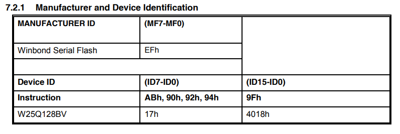
The flash I use is W25Q128. According to the manual, there is a general command 0x9F for reading flash models. If normal, the W25Q128 should return 0xEF4018
We refer to API Manual to initialize SPI first and create an SPI object spi_device = spi.deviceSetup(0,20,0,0,8,2000000,spi.MSB,1,1)
Send the 0x9F instruction to read the returned 3 bytes recv = spi_device:transfer(string.char(0x9f),nil,3)
The overall code is as follows. For the complete code, see the SPI folder in the demo directory.
sys.taskInit(
function()
local spi_device = spi.deviceSetup(0,20,0,0,8,2000000,spi.MSB,1,1)
while 1 do
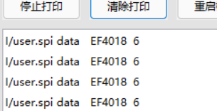
local recv = spi_device:transfer(string.char(0x9f),nil,3)
log.info("spi data",recv:toHex())
sys.wait(1000)
end
end
)
Downloaded to the device, you can see that the value printed in the log is EF4018 in accordance with the manual instructions, SPI communication is normal
SFUD-External flash#
This chapter will use W806 hardware SPI to mount flash to the file system, read and write directly
Introduction#
In the last chapter, we learned to use SPI to read the ID of external flash. In fact, the read and write instructions of external spi flash are compatible. In the process of daily use, it will be very troublesome if we directly use spi to read and write flash through instructions. As a result, LuatOS has designed a set of interfaces to realize abstract read and write of external spi flash through this set of interfaces and realize simple read and write of Lua io.
Hardware preparation#
W806 A development board, SPI flash a
Software usage#
Wiring diagram see SPI that chapter can not repeat
Refer to sfud Document to write a simple demo. The general idea is to create a spi hardware device object for sfud first, and then operate spi through sfud’s abstract interface to realize the operation of flash.
local spi_flash = spi.deviceSetup(0,20,0,0,8,2000000,spi.MSB,1,1)--PB6
log.info("sfud.init",sfud.init(spi_flash))
log.info("sfud.getDeviceNum",sfud.getDeviceNum())
local sfud_device = sfud.getDeviceTable()
log.info("sfud.write",sfud.write(sfud_device,1024,"sfud"))
log.info("sfud.read",sfud.read(sfud_device,1024,4))
First test whether the equipment can be connected normally and burn. Looking at the log, we can see that sfud’s library automatically helped us obtain flash’s manufacturer, size and other information during initialization. We also read and write normally through sfud.write() and read() interfaces.

But is that enough for us? No! We want to turn flash into a part of the file system and read and write directly through the native lua interface. According to the API’s instructions, we can find the function sfud.mount(), through which we can directly mount to the file system. mount is very similar to linux’s operation, is there any.
Next, practice and add the following code to the previous code.:
log.info("sfud.mount",sfud.mount(sfud_device,"/sfud"))
log.info("fsstat", fs.fsstat("/sfud"))
f = io.open ("/sfud/a.txt", "wb")
f:write(string.rep("1234567890", 100))
f:close()
log.info("fsize", fs.fsize("/sfud/a.txt"))
f = io.open ("/sfud/a.txt", "rb")
local data = f:read("*a")
log.info("fs", "data", data)
After we mount it to the file system, create a new file and write 1000 bytes of data, then read the file size, and then read the contents of the file.
Complete code in demo sfud folder
Burn to see the effect
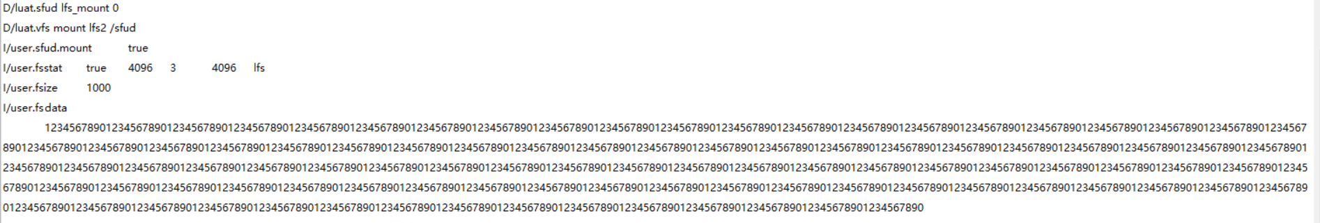
Fully in line with expectations, can directly operate flash through the file system, is not very convenient.
SDIO#
This chapter will learn to use the SDIO interface to drive the TF card and mount the TF card to the file system for reading and writing.
Introduction#
In the last chapter, we learned to mount flash directly with sfud, but spi is a bit slow on the two data lines and flash capacity is limited. At this time, I thought of a higher-speed SDIO interface. The SDIO interface was designed to read and write SD cards at the beginning. Later, it was also used in many high-speed communications.
Hardware preparation#
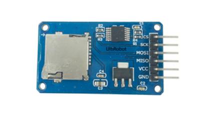
W806 Development board a piece, support SDIO tf card or SD card module. Be sure to be similar to the figure below that supports SDIO 4 data lines.
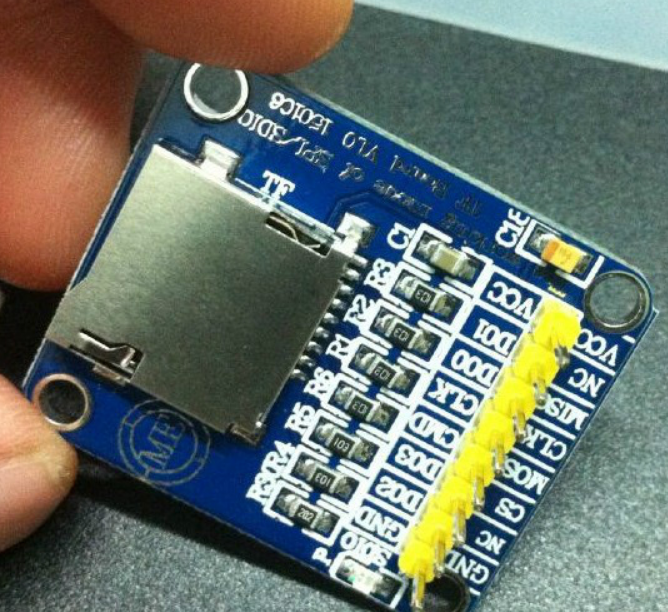
Do not support this only SPI
Software usage#
First look at the document LuatOS document and study how to connect the wires.
PB_06 |
GPIO_22 / UART1_TX / SDIO_CLK |
|---|---|
PB_07 |
GPIO_23 / UART1_RX / SDIO_CMD |
PB_08 |
GPIO_24 / SDIO_D0 |
PB_09 |
GPIO_25 / SDIO_D1 |
PB_10 |
GPIO_26 / SDIO_D2 |
PB_11 |
GPIO_27 / SDIO_D3 |
According to this way to connect the module, don’t forget to put the card.
Next, find API document, and sfud a routine, initialize the hardware, read and write tests (it is better not to do this test, direct read and write sd card insertion windows are not recognized), I will be unexpected
For the part that is directly mounted, except for the first two sentences, the rest is all native interfaces. Like sfud, it is directly used after mounting. The complete code is in demo’s sdio folder.
sdio.init(0)
sdio.sd_mount(0, "/sd")
f = io.open ("/sd/a.txt", "wb")
f:write(string.rep("1234567890", 100))
f:close()
log.info("fsize", fs.fsize("/sd/a.txt"))
f = io.open ("/sd/a.txt", "rb")
local data = f:read("*a")
log.info("fs", "data", data)
Burn and see the results.
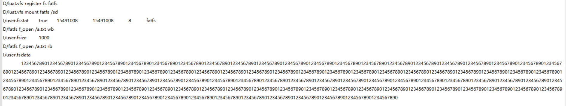
SD The card is so simple to use for the first time, and two lines of code are done.
LCD#
In this chapter, we will learn how to drive the LCD screen and display Chinese characters and graphics on the screen.
Introduction#
Usually driving the screen is a very complicated thing, because the LCD screen has a lot of instructions, display data and make a font. LuatOS encapsulates the LCD and has a variety of commonly used screen drivers built in. If it is not in the list, it can also be driven by Lua script configuration instructions. Using the idea of virtual video memory, the hardware driver and image drawing are extracted, which is more simple and convenient to use.
Hardware preparation#
W806 A development board, SPI screen, I use ST7735
Software usage#
As usual, first look at the document LuatOS Document to study how to connect the wires. Only the first two pins must use the solution of this table. The latter can be connected casually. I recommend press my connection.
SCL |
PB2 |
18 |
|---|---|---|
SDA |
PB5 |
21 |
RES |
PB3 |
19 |
DC |
PB1 |
17 |
CS |
PB4 |
20 |
BL |
PB0 |
16 |
Next, the old rule is to look at [API](https://wiki.luatos.org/api/ LCD .html) with the same thinking. First, initialize the hardware and do other things. According to the description of the interface, we need to start with a spi object, and then configure pins such as RES and DC according to the hardware. I wrote the pin list before, so the initialization code is as follows
local spi_lcd = spi.deviceSetup(0,20,0,0,8,2000000,spi.MSB,1,1)
log.info("lcd.init",lcd.init("st7735",{port = "device",pin_dc = 17, pin_pwr = 16,pin_rst = 19,direction = 0,w = 128,h = 160,xoffset = 2,yoffset = 1},spi_lcd))
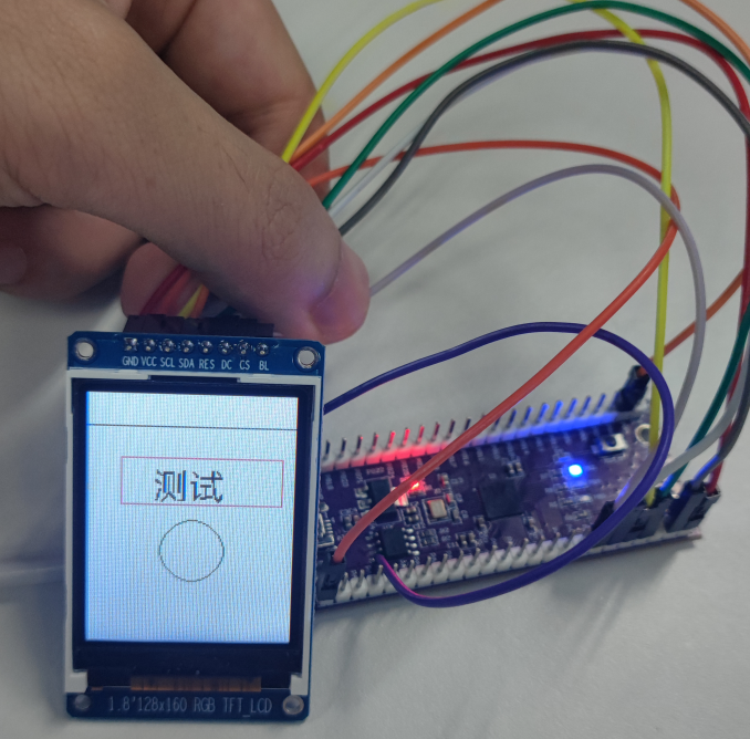
Next, I will study how to display something. I will simply draw a frame and a circle to display Chinese characters. The API is clearly written, so there is not much explanation here. The font in the place where the font is set can be selected during local compilation or cloud compilation as mentioned earlier. The settings here are also different if the selection is different. Attention should be paid. Complete code in the demo LCD file.
log.info("lcd.drawLine", lcd.drawLine(0,20,128,20,0x001F))
log.info("lcd.drawRectangle", lcd.drawRectangle(20,40,120,70,0xF800))
log.info("lcd.drawCircle", lcd.drawCircle(64,100,20,0x0CE0))
lcd.setFont(lcd.font_opposansm16_chinese)
lcd.drawStr(40,66,"Test")
Burn to view the effect
Try changing the screen, just change the initialization parameters, and the ili9341 will be driven.
log.info("lcd.init",lcd.init("ili9341",{port = "device",pin_dc = 17, pin_pwr = 16,pin_rst = 19,direction = 0,w = 240,h = 320,xoffset = 0,yoffset = 0},spi_lcd))
Look at the effect.
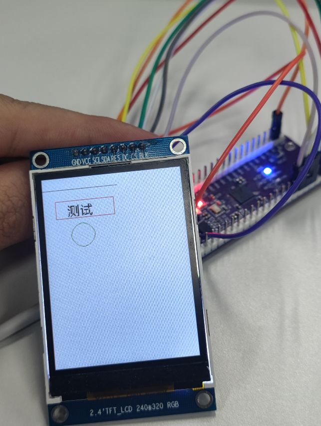
LuatOS The abstraction of display devices is worth learning.
LVGL#
This chapter will briefly introduce how to use LVGL to display a more beautiful picture
Introduction#
In the last chapter, I learned the LCD library and can smoothly draw dots and lines to display Chinese characters. However, if I want to see the interface well, these simple interfaces still cannot meet the requirements. As a result, there are many graphics libraries, LuatOS integrated LVGL graphics library, you can use a large number of controls to write a beautiful interface.
Hardware preparation#
W806 A development board, SPI screen, I use ST7735
Software usage#
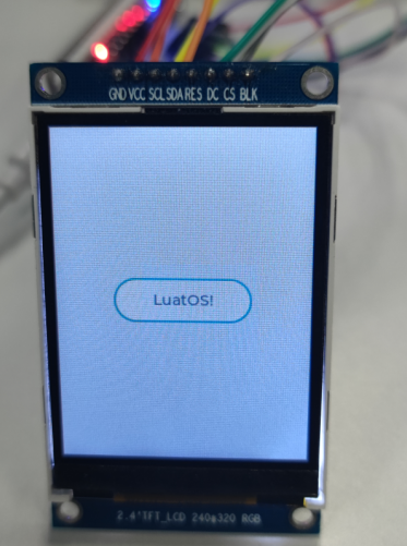
The chapter on LCD is not repeated. LVGL as a graphics library is the initialization screen of LCD first, and then LVGL is used to render the screen content. Directly on the code
log.info("lvgl", lvgl.init())
lvgl.disp_set_bg_color(nil, 0xFFFFFF)
local scr = lvgl.obj_create(nil, nil)
local btn = lvgl.btn_create(scr)
lvgl.obj_align(btn, lvgl.scr_act(), lvgl.ALIGN_CENTER, 0, 0)
local label = lvgl.label_create(btn)
lvgl.label_set_text(label, "LuatOS!")
lvgl.scr_load(scr)
Look at the effect, this button is much better than the one made by drawing lines.
For more LVGL tutorials, please refer to API and lvgl official documents.
RTC#
This chapter will introduce you to the RTC features of LuatOS. The value of the RTC will be read using the W806 development board and printed in the log.
Introduction#
RTC (Real-Time Clock)Real-time clock can provide accurate real-time time, it can be used to produce years, months, days, hours, minutes, seconds and other information. At present, most real-time clock chips use a crystal oscillator with high precision as the clock source. Some clock chips will add battery power to keep the time information valid in order to work when the main power supply is down.
Hardware preparation#
W806 A development board
Software usage#
Code display
log.info("os.date()", os.date())--Print Time
local t = rtc.get()--Get RTC Time
log.info("rtc", json.encode(t))--Print RTC Time
sys.wait(2000)--Delay
rtc.set({year=2021,mon=10,day=31,hour=17,min=8,sec=43})--rtc Time Settings
log.info("os.date()", os.date())--Print Time