Development Board#
The default will not automatically boot, to * * long press pwrkey key for 2 seconds to boot**
The power light is on when the power is connected, * * when the power light is on, it does not mean that the power is on * *, and COM equipment will only appear when the computer is connected and turned on.
Air780E Development board instructions V1.0.3.pdf
[Air780E Development Board Schematic V1.5(pdf version ).pdf](https://cdn.openluat-luatcommunity.openluat.com/attachment/20221028114557272_Air780E开发板原理图V1.5(pdf version).pdf)
Air780E Development board schematic diagram and PCB (Li Chuang EDA)
[Air780E Development board schematic and PCB(AD format).zip](https://cdn.openluat-luatcommunity.openluat.com/attachment/20221104135203881_780X开发板原理图和PCB(AD format).zip)
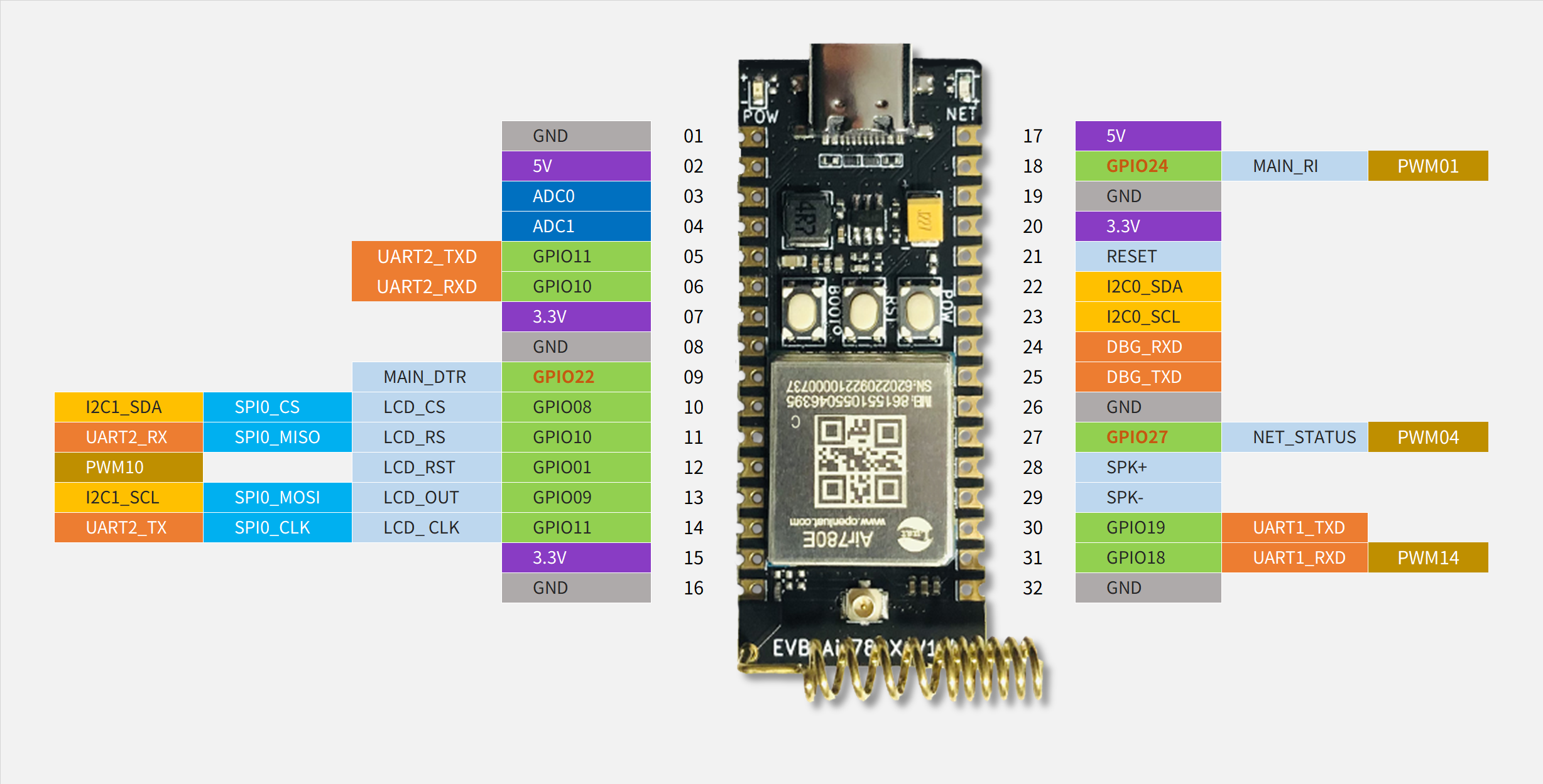
Development Board pinout#
This figure is LuatOS’s perspective. csdk supports adjusting pin multiplexing
The keys on the development board are BOOT(GPIO0), RESET (reset), PWR (power-on button) LED lights(GPIO27)
Development board pin size:
Distance between pins, 10mil, 2.54mm
Distance between two rows of pins, 700mil, 17.78mm
Reminder:
The one marked in red is AON_GPIO, which can also be used in sleep mode. It is normal in non-sleep mode.GPIO
UART2 Multiplexing GPIO11/GPIO10 with SPI0, no error
DBG UART0 is the underlying log output port. It is strongly recommended not to try to reuse it.
UART1 It is the main serial port and also supports downloading serial ports. It is strongly recommended not to reuse GPIO
AON_GPIO The driving ability is very weak!!
GPIO Both do not support “two-way trigger”, only one-way trigger is supported.
PWM The highest frequency is 13M
The LCD SPI in the figure is only a convention sort, in fact, it is a common SPI, not “dedicated””SPI
The IO level of the development board is 3.3v, and the module itself is configurable 1.8v/3.3v
SPK Is the speaker output, need external power amplifier, otherwise the sound is very small
PWM There are 4 available channels, 0/1/2/4 respectively, but they are mapped by 2 types respectively. There is a section after that.
The power lamp is uncontrolled and does not receive any GPIO