ESP32S3-CORE Development Board#
Special attention#
The driver of CH343 must be installed to download firmware normally when burning through USB to serial port. The default CDC driver can only print logs, but the download fails if the speed is too slow. Drive portal
Through USB download (USB direct connection) can be directly burned, Win8 and above systems do not need to install drivers. Luatools burning can be used normally, but LuatIDE cannot be used. In addition to the need to select the firmware with USB when burning, * GPIO19/20 will be occupied as USB pin *, should be avoided, other functions have no difference.
Note
Note that since win7 system does not have a winusb driver, and Microsoft has stopped supporting the system as early as 2020, if you need to USB download, please upgrade to win8 or above system, or go to Lexin Original Factory Manual to install the driver
Warning
The first batch of ESP32S3 core boards, due to FLASH thermal expansion and cold contraction, will have a small probability of causing virtual welding after hand. (Firmware will be burned before leaving the factory, and will not leave the factory until it is successfully burned. This is the reason )
If the default flashing light program on the back board cannot run and cannot burn firmware (stuck in the step of FLASH download), try to repair and solder the pad at FLASH (tin added )。
Therefore, please check the usb port with power on after you get it, and then carry out the welding needle arrangement operation after confirming that there is no problem.
Serial Burning Tutorial,Log baud rate is 921600
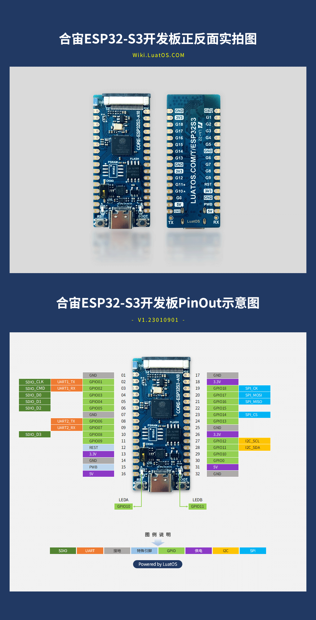
1. Product Description#
CORE ESP32S3 The core board is a core board designed based on Lexin ESP32-S3, with a size of only 21mm * 51mm. The board edge is designed with stamp holes, which is convenient for developers to use in different scenes. Core board onboard 2.4G antenna, support wifi and bluetooth. Core board built-in 8MB psram,16MB flash luxury configuration. Onboard ch343p USB to serial port chip, easy to download and burn; At the same time, an analog switch circuit is designed, which can be switched to S3 built-in USB with one key to develop and debug USB functions. The core board supports UART, GPIO, SPI, I2C, ADC, PWM,SDIO,Camera and other interfaces, and can be connected to peripherals for debugging according to actual needs.
2. hardware resources#
ESP32S3采用Xtensa® 32 Bit LX7 dual-core processor, five-stage pipeline architecture, frequency up to 240M. Built-in 512K SRAM, this release model and seal 8MB psram。
4 × SPI
1 × LCD Interface (8-bit ~ 16-bit parallel RGB, I8080, MOTO6800), supports conversion between RGB565, YUV422, YUV420, YUV411
1 × DVP 8 Bit to 16 bit camera interface
3 × UART
2 × I2C
2 × I2S
1 × RMT (TX/RX)
1 × Pulse Counter-LED PWM Controller, Up to 8 Channels
1 × Full Speed USB OTG
1 × USB Serial/JTAG Controller
2 × MCPWM
1 × SDIO Host interface with 2 card slots
General purpose DMA controller (GDMA),5 receive channels and 5 transmit channels
1 × TWAI® controller, compatible with ISO 11898-1(CAN specification 2.0)
2 × 12 Bit SAR ADC, up to 20 channels
3. Pin Definition#
Detailed Pin Description
**Number ** |
** Name ** |
** Default function after reset ** |
** Multiplexing function ** |
** Power domain ** |
** Pull-down capability** |
|---|---|---|---|---|---|
32 |
GND |
Grounding |
|||
31 |
5V |
5V Power interface, connected to USB VBUS |
|||
30 |
IO00 |
GPIO00,Input |
VDD3P3_CPU |
UP/DOWN |
|
29 |
IO10 |
GPIO10,input, output, high resistance |
VDD3P3_CPU |
UP/DOWN |
|
28 |
IO11 |
GPIO11,input, output, high resistance |
I2C_SDA |
VDD3P3_RTC |
UP/DOWN |
27 |
IO12 |
GPIO12,input, output, high resistance |
I2C_SCL |
VDD3P3_RTC |
UP/DOWN |
26 |
3.3V |
Chip power supply,3.3V |
|||
25 |
GND |
Grounding |
|||
24 |
IO13 |
GPIO13,input, output, high resistance |
VDD3P3_CPU |
UP/DOWN |
|
23 |
IO14 |
GPIO14,input, output, high resistance |
SPI2_CS |
VDD3P3_CPU |
UP/DOWN |
22 |
IO15 |
GPIO15,input, output, high resistance |
VDD3P3_CPU |
UP/DOWN |
|
21 |
IO16 |
GPIO16,input, output, high resistance |
SPI2_MISO |
VDD3P3_CPU |
UP/DOWN |
20 |
IO17 |
GPIO17,input, output, high resistance |
SPI2_MOSI |
VDD3P3_RTC |
UP/DOWN |
19 |
IO18 |
GPIO18,input, output, high resistance |
SPI2_CK |
VDD3P3_CPU |
UP/DOWN |
18 |
3.3V |
Chip power supply,3.3V |
|||
17 |
GND |
Grounding |
|||
16 |
5V |
5V Power interface, connected to USB VBUS |
|||
15 |
PWB |
Chip 3.3V power supply control, high level effective, no need to be suspended |
|||
14 |
GND |
Grounding |
|||
13 |
3.3V |
Chip power supply,3.3V |
|||
12 |
RESET |
Chip Reset |
VDD3P3_RTC |
||
11 |
IO09 |
GPIO09,input, output, high resistance |
VDD3P3_CPU |
UP/DOWN |
|
10 |
IO08 |
GPIO08,input, output, high resistance |
SDIO_D3 |
VDD3P3_CPU |
UP/DOWN |
09 |
IO07 |
GPIO07,input, output, high resistance |
UART2_RX |
VDD3P3_CPU |
UP/DOWN |
08 |
IO06 |
GPIO06,input, output, high resistance |
UART2_TX |
VDD3P3_CPU |
UP/DOWN |
07 |
GND |
Grounding |
|||
06 |
IO05 |
GPIO05,input, output, high resistance |
SDIO_D2 |
VDD3P3_CPU |
UP/DOWN |
05 |
IO04 |
GPIO04,input, output, high resistance |
SDIO_D1 |
VDD3P3_CPU |
UP/DOWN |
04 |
IO03 |
GPIO03,input, output, high resistance |
SDIO_D0 |
VDD3P3_CPU |
UP/DOWN |
03 |
IO02 |
GPIO2,input, output, high resistance |
UART1_RX/SDIO_CMD |
VDD3P3_CPU |
UP/DOWN |
02 |
IO01 |
GPIO1,input, output, high resistance |
UART1_TX/SDIO_CLK |
VDD3P3_CPU |
UP/DOWN |
01 |
GND |
Grounding |
Any GPIO can be used as a PWM pin, and the number is the same as that of GPIO, but only 8 PWMs can be turned on at the same time. Attention must be paid
The SPI of the development board is SPI 2
SPI 3 Corresponding IO:SPI3_MISO -> GPIO33、SPI3_MOSI -> GPIO47、SPI3_SCLK -> GPIO48
4. function introduction#
1. Power supply#
CORE-ESP32-S3 The core board supports the following 3 ways of power supply:
Type-C Interface power supply (default)
5V and GND pin supply
3V3 and GND pin supply

Power supply mode to be recommend preferentially during debugging: power supply TYPE-C USB interface.
2. LED Control#
The CORE ESP32S3 core board carries 2 LEDs. Developers can refer to Table 4-1 for control of corresponding pins.
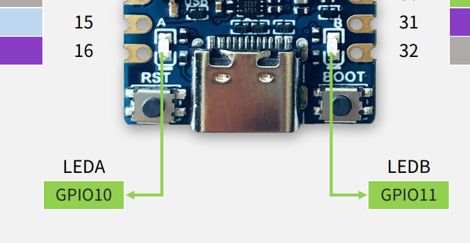
Table 4-1
LEDNumber |
Corresponds to GPIO |
Pin function |
Description |
|---|---|---|---|
LEDA |
IO10 |
GPIO10 Configuration |
Active High |
LEDB |
IO11 |
GPIO11 Configuration |
Active High |
3. Key introduction#
The CORE ESP32S3 core board carries two keys, of which BOOT key can realize BOOT download function, RST key can realize reset function, and pin control reference table 4-2。
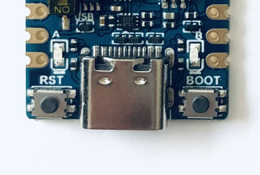
Table 4-2
**Key Number ** |
Pin Function |
** Description** |
|---|---|---|
BOOT/GPIO0 |
When the key is pressed, the chip enters download mode |
active low |
RST |
When the key is pressed, the chip reset |
active low |